
At Acentech, we routinely make vibration measurements in laboratory-grade buildings to characterize the floor vibrations. The floors in these buildings are usually very stiff and well-damped, which means any vibration disturbance dies out very quickly. Office buildings, by contrast, tend to have more flexible floors with long spans and modest damping (energy dissipation). As a result, the vibrations produced by a person walking on the floor can persist for a few seconds. Long-span structures like monumental stairs and footbridges can have even less damping than an office floor, possibly resulting in even more persistent vibrations as a result of excitation.
The devices often called Tuned Mass Dampers are more accurately referred to as Tuned Mass Absorbers. The term “absorber” better describes their function: they transfer vibrational energy from the primary structure into the absorber system, where it is dissipated. “Damper” is a common but less precise term since the device does not directly dampen vibrations, rather it absorbs them through a secondary process.
Steel and concrete do not have a lot of inherent energy dissipation, so structures made from said materials tend to be relatively lightly damped. Since damping is a key parameter affecting the vibration response, occasionally it is necessary to add damping augmentation to limit structural vibration.

The Millennium Footbridge in London, England, is a classic example where damping augmentation was used to mitigate excessive motion due to people walking across the bridge.
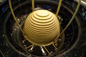
Very tall buildings are also examples of structures that can need a little assistance when it comes to damping their motion. A very large TMA is located at the top of Taipei 101 in Taiwan. If you ever get the chance to visit, you can actually visit the observatory to see it in action.
While the Millennium Bridge and Taipei 101 stories are highly interesting and worthy of a read on their own, in this blog I would like to talk about a smaller scale damping strategy that can be employed on much more modest structures. Specifically, I will discuss Tuned Mass Absorbers (TMAs).
THE THEORY
Let us assume that we have a simple mass/spring oscillator that is lightly damped. If we disturb the mass, it will bounce up and down at the system’s natural frequency with gradually diminishing amplitude. Eventually, the energy dissipation in the system will cause the motion to die out altogether. A pendulum is a good example of a lightly damped system that swings back and forth at its natural frequency with ever-diminishing amplitude, until the vibrations eventually die out.
On the other hand, if we apply an oscillatory force to the mass, the mass will move at the same frequency as the force, and eventually, the magnitude of the oscillation will reach a steady state. If we start at a very low frequency (well below resonance) and increase it slowly, an interesting thing will happen: the magnitude of the response will grow until we match the resonant frequency. If we keep turning the frequency up (above resonance), the response magnitude will decrease again.
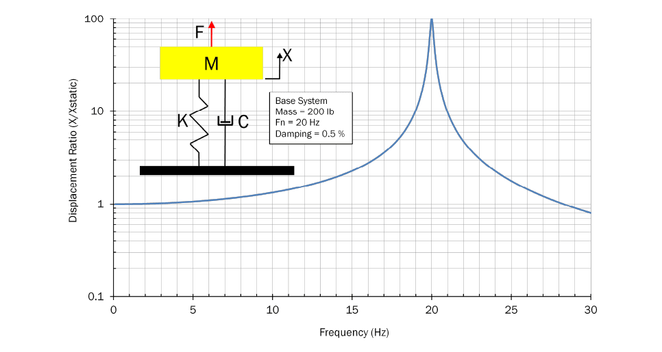
Figure 1 – Lightly Damped Spring/Mass Oscillator
Figure 1 shows the response of a mass/spring system to an oscillatory force. The system mass is 200lb. with a natural frequency of 20 Hz (cycles per second). The damping is 0.5% which is quite small. In the inset picture, K is the spring that supports the mass, and C provides the small amount of damping.
At very low frequencies, the response magnitude is essentially the same as if you applied a static force to the spring. At resonance, however, the response is 100x higher than the static deflection. Above resonance, the amplitude decreases as the frequency gets higher. If this curve predicted the response of a footbridge, it could be a real problem.
TUNED MASS ABSORBER (TMA)
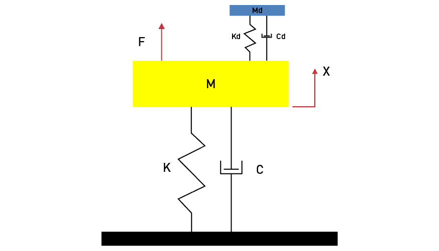
Figure 2: TMA Attached to Base Oscillator
As it turns out, if we attach another mass/spring system (the TMA) to the base system and tune it so it has the same natural frequency as the base system, it can help suppress the motion of the base system. The TMA must have more damping than the base system because all of the energy that was going into moving the base mass must now flow into, and be dissipated by, the absorber. Figure 2 shows the configuration of a TMA attached to the base system.
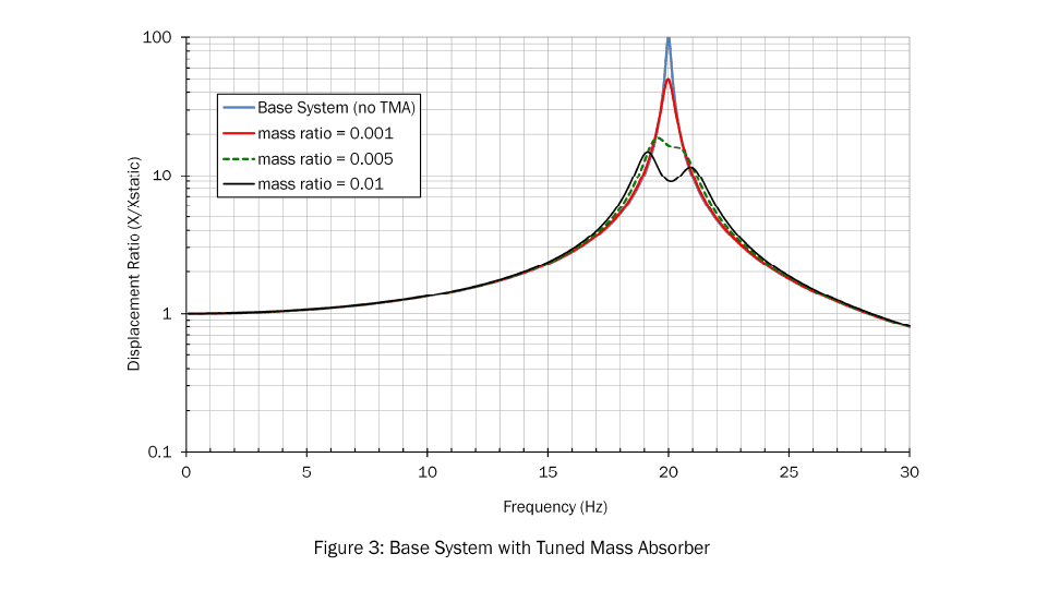
Figure 3 shows the predicted response of the base system with a tuned mass absorber attached. The figure shows the results for a 0.2lb. absorber, a 1lb. absorber, and a 2lb. absorber. As the figure shows, even an absorber as small as 0.2lb. can reduce the vibrations of the base system by half. The 1lb. absorber can reduce the vibrations 5x, but there are diminishing returns beyond that. Heavier absorbers can reduce the vibrations at the natural frequency, but they also create two side lobes where the vibrations are increased. This is a side effect of using a TMA to suppress vibration at one frequency; it might increase the vibrations at others.
A cautionary note on the 5x reduction with only a 0.5% mass addition. This might seem impressive, but the 5x is referenced to the low-damping starting point. If the base system has a reasonable amount of damping to begin with, the improvement will not be as stark.
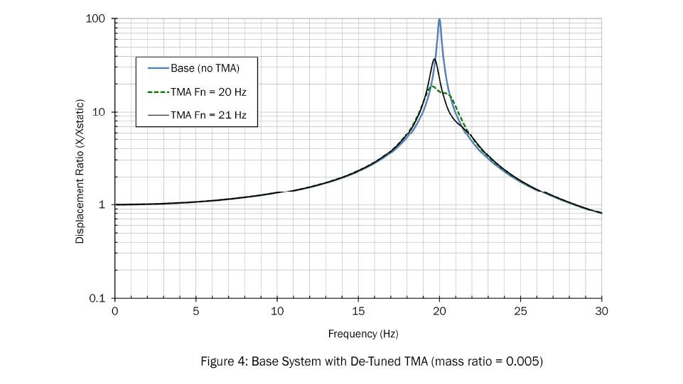
DETUNING OF THE BASE SYSTEM
The TMA is designed to match the natural frequency of the base system. If the frequency of the base system changes, or the TMA frequency is slightly off, the TMA will no longer be tuned to the correct frequency. To illustrate this, Figure 4 shows the response of the combined system assuming the TMA is tuned to 21 Hz, not 20 Hz (a 5% error in tuning). You can see how the de-tuned absorber is less effective than the absorber that is properly tuned. A de-tuned condition can also happen if there are changes in the base system (mass, stiffness) that affect its natural frequency.
EFFECTIVE MASS OF A TMA
We can get a little more insight into the workings of a TMA when we look at it from the perspective of the base structure. In that case, we ask what happens when we apply a force to the spring side of the TMA as shown in Figure 5.
The math is a little tricky, but we can calculate the dynamics of this system and express the results as an effective mass. Figure 6 shows how the effective mass varies with the driving frequency for three different levels of absorber internal damping. In the figure, the effective mass is expressed as a ratio to the static mass of the absorber (Md).
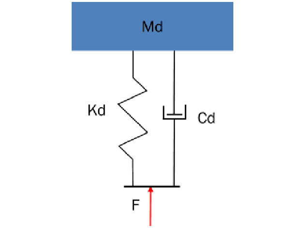
Figure 5: Effective Mass of a TMA
In Figure 6, you can see that the effective mass ratio at a very low frequency is equal to one for all three absorbers. This means that, at those very low frequencies, the apparent absorber mass is simply equal to the static mass of the absorber. As the driving frequency increases, the mass ratio exceeds one, which means the absorber appears to be heavier than it really is. The mass ratio peaks when the driving frequency matches the absorber’s design frequency (20 Hz). You can also see that the apparent mass is not constant; it depends on the damping in the absorber itself. If the absorber is lightly damped, it could appear to be 100x heavier than the actual physical mass. If the damping is higher, the apparent mass at resonance is less. The other thing to notice is that the absorber’s band of effective frequencies is also much narrower when the absorber is lightly damped. So, while a lightly damped absorber may be very effective at the design frequency, it is very susceptible to de tuning.
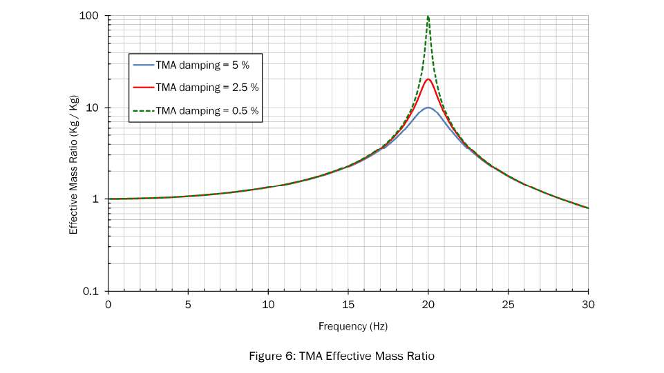
At high frequencies, the effective mass ratio is less than one, and if we continued the plot to higher frequencies, it would head toward zero. This means, at frequencies well above the design frequency, the base structure doesn’t even know the absorber is attached. But this is okay, since we are primarily interested in the behavior around the natural frequency of the base structure.
In physical terms, near the tuning frequency, it is like we are adding a “dynamically” very massive thing to the base structure, which helps us understand why the motion of the base structure is suppressed.
MULTIPLE TUNED MASS ABSORBERS
As it turns out, many of the limitations of a single TMA can be overcome if we consider our absorber to be a collection of TMAs, all tuned to a slightly different frequency. By selecting the frequency range, we can create an absorber that is effective over a broader range of frequencies, making the TMA less sensitive to de-tuning.
And, by using multiple absorbers, we can achieve the same effective mass with lighter individual units. For example, we can use ten 2lb. absorbers rather than one 20lb. absorber. Also, for a multi-absorber system, each absorber requires less internal damping, making them easier to design and fabricate.
Image Credits: Armand du Plessis, Taipei 101 Tuned Mass Damper 2010, CC BY 3.0
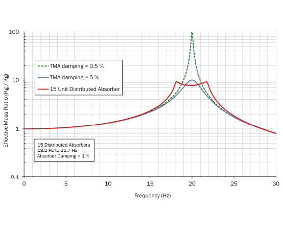
Figure 7: Effective Mass Ratio Comparison – Single TMA and Multiple TMAs
Figure 7 compares the effective mass of a single TMA to a distributed system with 15 individual units tuned to frequencies from 18.2 Hz to 21.7 Hz. You can see how the effective mass is not concentrated at one frequency but rather is distributed across a range of frequencies.
Figure 8 shows the response of the base system when the distributed TMA is attached. In the figure, the single TMA and the distributed TMA both have the same total mass. You can see how the distributed system was able to reduce the side lobes, albeit at the expense of slightly worse performance at the resonant frequency of the base system. Also, note that the distributed system was able to do this with much less damping per absorber, 1% compared to 5% for the single TMA. This is important because it is generally easier to fabricate mechanical oscillators with low levels of damping.
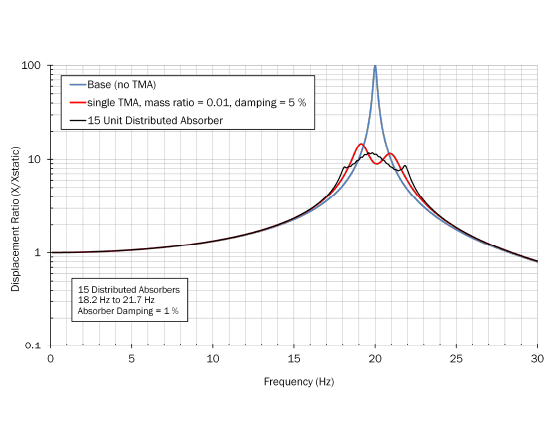
Figure 8: Base System with Single TMA and Multiple TMAs
To illustrate how effective a distributed TMA can be, I fabricated a base system with very little damping. You can see that when it is disturbed, the vibrations persist for a very long time. I then designed a simple distributed absorber with 12 elements. In the second video you can see how quickly the base vibrations die out when the absorber is attached. You can also see how the vibration energy is transferred from the base system into the absorber elements.
LET’S GET CREATIVE
One of the attractive things about distributed systems is that the design frequencies do not have to follow any specific pattern. So, one can create a distributed absorber that provides a specific base system response. Say, for example, we wanted a distributed system that limited the base system response ratio, (as shown in Figure 8) to a maximum value of 10.
We can do this using an iterative optimization process. Figure 9 shows the results of an optimization run that was designed to limit the displacement ratio to 10. This particular absorber had 100 elements, each with a damping factor of just 0.5%. As the figure shows, with this design, we are able to limit the response ratio of the combined system to 10 over a wide range of frequencies.
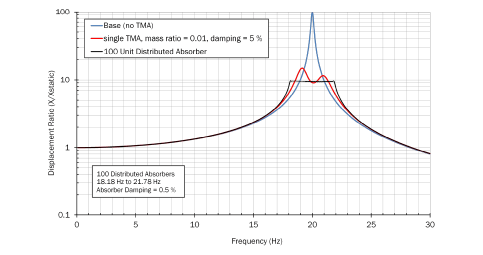
Figure 9: Base System with Single TMA and 100 Optimized TMA’s
You might wonder about the cost and complexity of fabricating a distributed system with 100 individual units. However, we can be creative in the way we approach this. For example, if we use cantilever beams as springs, we can adjust the frequency of each beam with prescribed masses at the end of the beam. The mass added would be determined by the desired frequency of each element.
CLOSING THOUGHTS
Tuned mass absorbers offer a unique way to treat excessive vibration in a structure. A single absorber can achieve a great deal, but if we expand our design scope to include a distribution of absorbers, we can tailor our damping treatment to achieve even better outcomes.